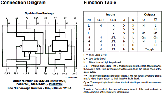
Dual J-K Flip-Flops With Preset And Clear datasheet 2015-02-27В В· This feature is not available right now. Please try again later.
J-K Flip-Flop
SOLUTION FOR MORE EXERCISES FOR MIDTERM # 2. 2018-08-11 · In this article, let’s learn about different types of flip flops used in digital electronics. Basic Flip Flops in Digital Electronics. This article deals with the basic flip flop circuits like S-R Flip Flop, J-K Flip Flop, D Flip Flop, and T Flip Flop along with truth tables and their corresponding circuit symbols., 74LS76 Datasheet, 74LS76 PDF, 74LS76 Data sheet, 74LS76 manual, 74LS76 pdf, 74LS76, datenblatt, Electronics 74LS76, alldatasheet, free, datasheet, Datasheets, data.
IndiaBIX provides you lots of fully solved Digital Electronics (Flip-Flops) questions and answers with Explanation. Solved examples with detailed answer description, explanation are given and it would be easy to understand. All students, freshers can download Digital Electronics Flip-Flops quiz questions with answers as PDF files and eBooks. 2017-06-01В В· JK Flip Flop Truth Table and Circuit Diagram. JK Flip Flop By Sasmita June 1, 2017. Before we learn what a JK flip flop is, it would be wise to learn what, actually, a flip flop is. A flip-flop is a bistable circuit made up of logic gates. A bistable circuit can exist in either of two stable states indefinitely and can be made to change its state by means of some external signal. The most
February 13, 2012 ECE 152A - Digital Design Principles 2 Reading Assignment Brown and Vranesic 7Flip-Flops, Registers, Counters and a Simple Processor 7.5 T Flip-Flop 7.5.1 Configurable Flip-Flops 7.6 JK Flip-Flop 7.7 Summary of Terminology 7.8 Registers 7.8.1 … 2018-08-11 · D Flip Flop to JK Flip Flop; In this conversion, D is the actual input to the flip flop and J and K are the external inputs. J, K and Qp make eight possible combinations, as shown in the conversion table below. D is expressed in terms of J, K and Qp.
JK flip-flop is a term for some of the particular physics involved in the circuit building which goes into all sorts of electronics. These types of engineering terms apply to laptop or desktop computer motherboards, mobile device circuitry, or any other type of electronics design. sn5476, sn54ls76a sn7476, sn74ls76a dual j-k flip-flops with preset and clear sdls121 – december 1983 – revised march 1988 2 post office box 655303 • dallas, texas 75265
From the function tables shown in Fig. 7.4, 7.10, 7.17, and 7.20 of the flip-flops learnt earlier in Chapter 7, the excitation or characteristic table of SR flip-flop, D flip-flip, JK flip-flop, and T flip-flop are shown in Fig. 9.7. and 9.8 respectively. Q t is denotes the output of the present state and Q t+1 denotes the The fact that J-K flip-flop only "latches" the J-K inputs on a transition from 1 to 0 makes it much more useful as a memory device. J-K flip-flops are also extremely useful in counters (which are used extensively when creating a digital clock). Here is an example of a 4-bit counter using J-K flip-flops:
2015-02-27 · This feature is not available right now. Please try again later. Solution : Problem I I. JK flip-flop next state table D flip-flop excitation table Q Qnext D 0 0 0 0 1 1 1 0 0 1 1 1 Excitation table D = JQ’ + K’Q . Solution : Problem II The state table is derived as below : ( T 1 , T0 values also shown here, but they don’t form a part of the state table ) : 20 points
JK Flip Flop. One of the most useful and versatile flip flop is the JK flip flop the unique features of a JK flip flop are: If the J and K input are both at 1 and the clock pulse is applied, then the output will change state, regardless of its previous condition. SOLUTION FOR MORE EXERCISES FOR MIDTERM # 2 1. (Flip-Flops) a. What is the difference between a latch and a flip flop? SOLUTION: Latch is a level sensitive device. Flip-flops are edge sensitive devices. b. Implement a JK flip-flop with a T flip-flop and a minimal AND-OR-NOT network. Let us assume that the complements of J, K and Q signals are
2018-08-11В В· D Flip Flop to JK Flip Flop; In this conversion, D is the actual input to the flip flop and J and K are the external inputs. J, K and Qp make eight possible combinations, as shown in the conversion table below. D is expressed in terms of J, K and Qp. 2015-02-27В В· This feature is not available right now. Please try again later.
From the function tables shown in Fig. 7.4, 7.10, 7.17, and 7.20 of the flip-flops learnt earlier in Chapter 7, the excitation or characteristic table of SR flip-flop, D flip-flip, JK flip-flop, and T flip-flop are shown in Fig. 9.7. and 9.8 respectively. Q t is denotes the output of the present state and Q t+1 denotes the Clocked J-K FF (a) Clocked J-K flip-flop that responds only to the positive edge of the clock; (b) waveforms. J=K=1 condition does not result in an ambiguous output E1.2 Digital Electronics I 9.20 Nov 2007 Internal circuitry of edge-triggered J-K flip-flop
The 74HC112; 74HCT112 is a dual negative-edge triggered JK flip-flop. It features individual J and K inputs, clock (nCP) set (nSD) and reset (nRD) inputs. It also has complementary nQ and nQ outputs. The set and reset are asynchronous active LOW inputs and operate independently of the clock input. The J and K inputs control the state FLIP FLOPS This article deals with the basic flip flop circuits like S-R Flip Flop, J-K Flip Flop, D Flip Flop, and T Flip Flop along with truth tables and their corresponding circuit symbols. Flip flops are actually an application of logic gates. With the help of Boolean logic you can create memory with them. Flip flops can also be considered
JK flip-flop is a term for some of the particular physics involved in the circuit building which goes into all sorts of electronics. These types of engineering terms apply to laptop or desktop computer motherboards, mobile device circuitry, or any other type of electronics design. JK Flip Flop. One of the most useful and versatile flip flop is the JK flip flop the unique features of a JK flip flop are: If the J and K input are both at 1 and the clock pulse is applied, then the output will change state, regardless of its previous condition.
Clocked J-K FF (a) Clocked J-K flip-flop that responds only to the positive edge of the clock; (b) waveforms. J=K=1 condition does not result in an ambiguous output E1.2 Digital Electronics I 9.20 Nov 2007 Internal circuitry of edge-triggered J-K flip-flop JK flip-flop is a term for some of the particular physics involved in the circuit building which goes into all sorts of electronics. These types of engineering terms apply to laptop or desktop computer motherboards, mobile device circuitry, or any other type of electronics design.
4027B Dual JK Flip Flop - DataSheetGo.com

SR Flip Flop to JK Flip Flop Conversion YouTube. 2018-05-15 · Master Slave flip flop are the cascaded combination of two flip-flops among which the first is designated as master flip-flop while the next is called slave flip-flop (Figure 1). Here the master flip-flop is triggered by the external clock pulse train while the slave is activated at its inversion i.e.…, sn5476, sn54ls76a sn7476, sn74ls76a dual j-k flip-flops with preset and clear sdls121 – december 1983 – revised march 1988 2 post office box 655303 • dallas, texas 75265.
What is a race around condition related to JK Flip Flop. FLIP FLOPS This article deals with the basic flip flop circuits like S-R Flip Flop, J-K Flip Flop, D Flip Flop, and T Flip Flop along with truth tables and their corresponding circuit symbols. Flip flops are actually an application of logic gates. With the help of Boolean logic you can create memory with them. Flip flops can also be considered, JK flip flop is a refined & improved version of SR Flip Flop. that has been introduced to solve the problem of indeterminate state. that occurs in SR flip flop when both the inputs are 1..
What is a JK Flip Flop? Quora
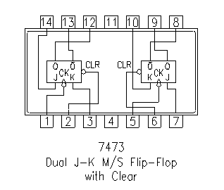
What is a JK Flip Flop? Quora. The fact that J-K flip-flop only "latches" the J-K inputs on a transition from 1 to 0 makes it much more useful as a memory device. J-K flip-flops are also extremely useful in counters (which are used extensively when creating a digital clock). Here is an example of a 4-bit counter using J-K flip-flops: https://el.wikipedia.org/wiki/Flip-flop SOLUTION FOR MORE EXERCISES FOR MIDTERM # 2 1. (Flip-Flops) a. What is the difference between a latch and a flip flop? SOLUTION: Latch is a level sensitive device. Flip-flops are edge sensitive devices. b. Implement a JK flip-flop with a T flip-flop and a minimal AND-OR-NOT network. Let us assume that the complements of J, K and Q signals are.
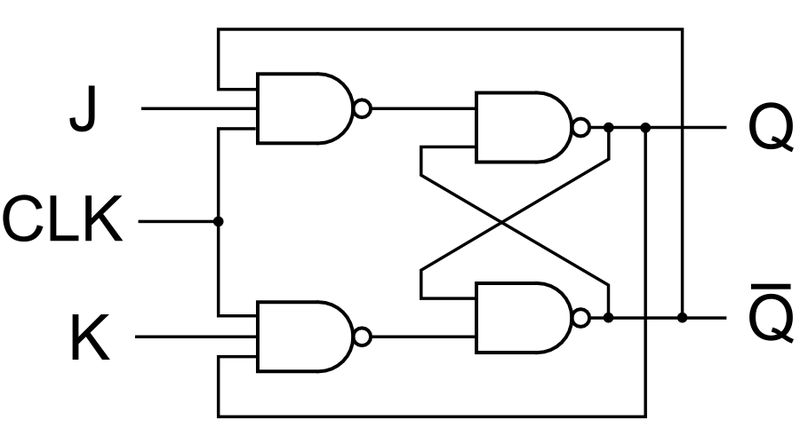
sn5476, sn54ls76a sn7476, sn74ls76a dual j-k flip-flops with preset and clear sdls121 – december 1983 – revised march 1988 2 post office box 655303 • dallas, texas 75265 The 74HC112; 74HCT112 is a dual negative-edge triggered JK flip-flop. It features individual J and K inputs, clock (nCP) set (nSD) and reset (nRD) inputs. It also has complementary nQ and nQ outputs. The set and reset are asynchronous active LOW inputs and operate independently of the clock input. The J and K inputs control the state
JK Flip Flop. The flip flop is a basic building block of sequential logic circuits. It is a circuit that has two stable states and can store one bit of state information. The output changes state by signals applied to one or more control inputs. The basic JK Flip Flop has J,K … February 13, 2012 ECE 152A - Digital Design Principles 2 Reading Assignment Brown and Vranesic 7Flip-Flops, Registers, Counters and a Simple Processor 7.5 T Flip-Flop 7.5.1 Configurable Flip-Flops 7.6 JK Flip-Flop 7.7 Summary of Terminology 7.8 Registers 7.8.1 …
2015-07-27В В· A flip-flop is a bistable device. its output remains either low or high. The high state is 1 called SET state and Low state is 0 called RESET state. JK flipflop is most versatile flipflop and most commonly used when descrete devices are used to im... 2017-06-01В В· JK Flip Flop Truth Table and Circuit Diagram. JK Flip Flop By Sasmita June 1, 2017. Before we learn what a JK flip flop is, it would be wise to learn what, actually, a flip flop is. A flip-flop is a bistable circuit made up of logic gates. A bistable circuit can exist in either of two stable states indefinitely and can be made to change its state by means of some external signal. The most
2017-06-01 · JK Flip Flop Truth Table and Circuit Diagram. JK Flip Flop By Sasmita June 1, 2017. Before we learn what a JK flip flop is, it would be wise to learn what, actually, a flip flop is. A flip-flop is a bistable circuit made up of logic gates. A bistable circuit can exist in either of two stable states indefinitely and can be made to change its state by means of some external signal. The most Solution : Problem I I. JK flip-flop next state table D flip-flop excitation table Q Qnext D 0 0 0 0 1 1 1 0 0 1 1 1 Excitation table D = JQ’ + K’Q . Solution : Problem II The state table is derived as below : ( T 1 , T0 values also shown here, but they don’t form a part of the state table ) : 20 points
2018-03-10В В· JK flip flop circuit can also be referred to as a gated SR flip flop which has an additional unit that is clock input. There is an additional clock input, because it prevents the invalid conditions which can occur during the set and reset inputs. Edge-triggered J-K flip-flop The J-K flip-flop works very similar to S-R flip-flop. The only difference is that this flip-flop has NO invalid state. The outputs toggle (change to the opposite state) wh enboth J and K inputsare HIGH. Edge-triggered D flip-flop The operations of a D flip-flop is much more simpler. It has only one input addition
Step 6: Now transfer the JK states of the flip-flop inputs from the excitation table to Karnaugh maps in Tables 2.3–2.8 to derive a simplified Boolean expression for each flip- flop input. Nexperia HEF4027B Dual JK flip-flop [1] The typical values of the propagation delay and transition times are calculated from the extrapolation formulas shown (CL in pF). [2] tt is the same as tTLH and tTHL. Table 8. Dynamic power dissipation P 12. Waveforms fmax maximum frequency CP input; J = K = HIGH; see Figure 5 5 V 4 8 - MHz 10 V 12 25
2015-07-27 · A flip-flop is a bistable device. its output remains either low or high. The high state is 1 called SET state and Low state is 0 called RESET state. JK flipflop is most versatile flipflop and most commonly used when descrete devices are used to im... 2017-08-06 · It’s a type of flip flop that is edge triggered, i.e. changes happen on the indicated edge of the clock. It has two inputs called J & K and it has a clock input. It usually has both Q and Q_bar outputs. It works according to this truth table: Most...
The 74HC112; 74HCT112 is a dual negative-edge triggered JK flip-flop. It features individual J and K inputs, clock (nCP) set (nSD) and reset (nRD) inputs. It also has complementary nQ and nQ outputs. The set and reset are asynchronous active LOW inputs and operate independently of the clock input. The J and K inputs control the state 2017-10-11В В· 4027B - Dual JK Flip Flop, Circuit, Pinout, Schematic, Equivalent, Replacement, Data, Sheet, Manual and Application notes. You can datasheet PDF files download.
The fact that J-K flip-flop only "latches" the J-K inputs on a transition from 1 to 0 makes it much more useful as a memory device. J-K flip-flops are also extremely useful in counters (which are used extensively when creating a digital clock). Here is an example of a 4-bit counter using J-K flip-flops: JK Flip-flop. Due to the undefined state in the SR flip flop, another flip flop is required in electronics. The JK flip flop is an improvement on the SR flip flop where S=R=1 is not a problem. JK Flip-Flop. The input condition of J=K=1, gives an output inverting the output state. However, the outputs are the same when one tests the circuit
Step 6: Now transfer the JK states of the flip-flop inputs from the excitation table to Karnaugh maps in Tables 2.3–2.8 to derive a simplified Boolean expression for each flip- flop input. JK Flip Flop. The flip flop is a basic building block of sequential logic circuits. It is a circuit that has two stable states and can store one bit of state information. The output changes state by signals applied to one or more control inputs. The basic JK Flip Flop has J,K …
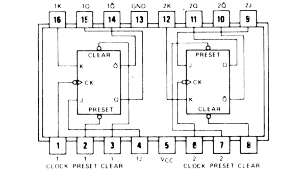
2018-08-11 · In this article, let’s learn about different types of flip flops used in digital electronics. Basic Flip Flops in Digital Electronics. This article deals with the basic flip flop circuits like S-R Flip Flop, J-K Flip Flop, D Flip Flop, and T Flip Flop along with truth tables and their corresponding circuit symbols. 2017-06-01 · JK Flip Flop Truth Table and Circuit Diagram. JK Flip Flop By Sasmita June 1, 2017. Before we learn what a JK flip flop is, it would be wise to learn what, actually, a flip flop is. A flip-flop is a bistable circuit made up of logic gates. A bistable circuit can exist in either of two stable states indefinitely and can be made to change its state by means of some external signal. The most
SR Flip Flop to JK Flip Flop Conversion YouTube

Module-3 S LOGIC CIRCUITS. 2018-03-10 · JK flip flop circuit can also be referred to as a gated SR flip flop which has an additional unit that is clock input. There is an additional clock input, because it prevents the invalid conditions which can occur during the set and reset inputs., February 13, 2012 ECE 152A - Digital Design Principles 2 Reading Assignment Brown and Vranesic 7Flip-Flops, Registers, Counters and a Simple Processor 7.5 T Flip-Flop 7.5.1 Configurable Flip-Flops 7.6 JK Flip-Flop 7.7 Summary of Terminology 7.8 Registers 7.8.1 ….
What is a race around condition related to JK Flip Flop
Solution Problem I. The J-K flip-flop is the most versatile of the basic flip-flops.It has the input- following character of the clocked D flip-flop but has two inputs,traditionally labeled J and K. If J and K are different then the output Q takes the value of J at the next clock edge., 2015-07-27В В· A flip-flop is a bistable device. its output remains either low or high. The high state is 1 called SET state and Low state is 0 called RESET state. JK flipflop is most versatile flipflop and most commonly used when descrete devices are used to im....
sn54107, sn54ls107a, sn74107, sn74ls107a dual j-k flip-flops with clear sdls036 – december 1983 – revised march 1988 2 post office box 655303 • dallas, texas 75265 IndiaBIX provides you lots of fully solved Digital Electronics (Flip-Flops) questions and answers with Explanation. Solved examples with detailed answer description, explanation are given and it would be easy to understand. All students, freshers can download Digital Electronics Flip-Flops quiz questions with answers as PDF files and eBooks.
FLIP FLOPS This article deals with the basic flip flop circuits like S-R Flip Flop, J-K Flip Flop, D Flip Flop, and T Flip Flop along with truth tables and their corresponding circuit symbols. Flip flops are actually an application of logic gates. With the help of Boolean logic you can create memory with them. Flip flops can also be considered SOLUTION FOR MORE EXERCISES FOR MIDTERM # 2 1. (Flip-Flops) a. What is the difference between a latch and a flip flop? SOLUTION: Latch is a level sensitive device. Flip-flops are edge sensitive devices. b. Implement a JK flip-flop with a T flip-flop and a minimal AND-OR-NOT network. Let us assume that the complements of J, K and Q signals are
JK Flip Flop. The flip flop is a basic building block of sequential logic circuits. It is a circuit that has two stable states and can store one bit of state information. The output changes state by signals applied to one or more control inputs. The basic JK Flip Flop has J,K … Step 6: Now transfer the JK states of the flip-flop inputs from the excitation table to Karnaugh maps in Tables 2.3–2.8 to derive a simplified Boolean expression for each flip- flop input.
The two most widely flip-flops used in the design of sequential circuits are the D-Type flip-flop and the JK-Type flip-flop. The D-type flip-flop finds applications in registers and certain types of memories and the JK-type flip-flop is used in building counter circuits. 2 74LS76 Datasheet, 74LS76 PDF, 74LS76 Data sheet, 74LS76 manual, 74LS76 pdf, 74LS76, datenblatt, Electronics 74LS76, alldatasheet, free, datasheet, Datasheets, data
The J-K flip-flop is the most versatile of the basic flip-flops.It has the input- following character of the clocked D flip-flop but has two inputs,traditionally labeled J and K. If J and K are different then the output Q takes the value of J at the next clock edge. 74LS76 Datasheet, 74LS76 PDF, 74LS76 Data sheet, 74LS76 manual, 74LS76 pdf, 74LS76, datenblatt, Electronics 74LS76, alldatasheet, free, datasheet, Datasheets, data
2015-07-27 · A flip-flop is a bistable device. its output remains either low or high. The high state is 1 called SET state and Low state is 0 called RESET state. JK flipflop is most versatile flipflop and most commonly used when descrete devices are used to im... sn5476, sn54ls76a sn7476, sn74ls76a dual j-k flip-flops with preset and clear sdls121 – december 1983 – revised march 1988 2 post office box 655303 • dallas, texas 75265
The J-K flip-flop is the most versatile of the basic flip-flops.It has the input- following character of the clocked D flip-flop but has two inputs,traditionally labeled J and K. If J and K are different then the output Q takes the value of J at the next clock edge. The fact that J-K flip-flop only "latches" the J-K inputs on a transition from 1 to 0 makes it much more useful as a memory device. J-K flip-flops are also extremely useful in counters (which are used extensively when creating a digital clock). Here is an example of a 4-bit counter using J-K flip-flops:
SOLUTION FOR MORE EXERCISES FOR MIDTERM # 2 1. (Flip-Flops) a. What is the difference between a latch and a flip flop? SOLUTION: Latch is a level sensitive device. Flip-flops are edge sensitive devices. b. Implement a JK flip-flop with a T flip-flop and a minimal AND-OR-NOT network. Let us assume that the complements of J, K and Q signals are From the function tables shown in Fig. 7.4, 7.10, 7.17, and 7.20 of the flip-flops learnt earlier in Chapter 7, the excitation or characteristic table of SR flip-flop, D flip-flip, JK flip-flop, and T flip-flop are shown in Fig. 9.7. and 9.8 respectively. Q t is denotes the output of the present state and Q t+1 denotes the
FLIP FLOPS This article deals with the basic flip flop circuits like S-R Flip Flop, J-K Flip Flop, D Flip Flop, and T Flip Flop along with truth tables and their corresponding circuit symbols. Flip flops are actually an application of logic gates. With the help of Boolean logic you can create memory with them. Flip flops can also be considered IndiaBIX provides you lots of fully solved Digital Electronics (Flip-Flops) questions and answers with Explanation. Solved examples with detailed answer description, explanation are given and it would be easy to understand. All students, freshers can download Digital Electronics Flip-Flops quiz questions with answers as PDF files and eBooks.
From the function tables shown in Fig. 7.4, 7.10, 7.17, and 7.20 of the flip-flops learnt earlier in Chapter 7, the excitation or characteristic table of SR flip-flop, D flip-flip, JK flip-flop, and T flip-flop are shown in Fig. 9.7. and 9.8 respectively. Q t is denotes the output of the present state and Q t+1 denotes the JK flip flop is a refined & improved version of SR Flip Flop. that has been introduced to solve the problem of indeterminate state. that occurs in SR flip flop when both the inputs are 1.
4027B Dual JK Flip Flop - DataSheetGo.com. To synthesize a D flip-flop, simply set K equal to the complement of J. Similarly, to synthesize a T flip-flop, set K equal to J. The JK flip-flop is therefore a universal flip-flop, because it can be configured to work as an SR flip-flop, a D flip-flop, or a T flip-flop. The characteristic equation of the JK flip-flop is:, sn5476, sn54ls76a sn7476, sn74ls76a dual j-k flip-flops with preset and clear sdls121 – december 1983 – revised march 1988 2 post office box 655303 • dallas, texas 75265.
J-K Flip-Flop
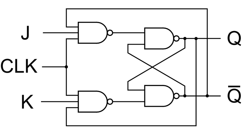
SOLUTION FOR MORE EXERCISES FOR MIDTERM # 2. sn54107, sn54ls107a, sn74107, sn74ls107a dual j-k flip-flops with clear sdls036 – december 1983 – revised march 1988 2 post office box 655303 • dallas, texas 75265, FLIP FLOPS This article deals with the basic flip flop circuits like S-R Flip Flop, J-K Flip Flop, D Flip Flop, and T Flip Flop along with truth tables and their corresponding circuit symbols. Flip flops are actually an application of logic gates. With the help of Boolean logic you can create memory with them. Flip flops can also be considered.
JK Flip Flop [Explained] in Detail eeeproject.com. To synthesize a D flip-flop, simply set K equal to the complement of J. Similarly, to synthesize a T flip-flop, set K equal to J. The JK flip-flop is therefore a universal flip-flop, because it can be configured to work as an SR flip-flop, a D flip-flop, or a T flip-flop. The characteristic equation of the JK flip-flop is:, JK Flip Flop. The flip flop is a basic building block of sequential logic circuits. It is a circuit that has two stable states and can store one bit of state information. The output changes state by signals applied to one or more control inputs. The basic JK Flip Flop has J,K ….
Dual J-K Flip-Flops With Clear datasheet
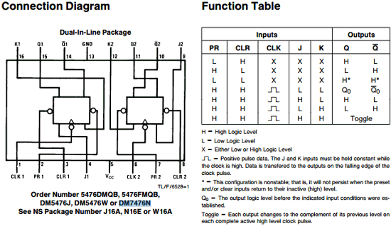
The J-K Flip-Flop HowStuffWorks. 2017-08-06 · It’s a type of flip flop that is edge triggered, i.e. changes happen on the indicated edge of the clock. It has two inputs called J & K and it has a clock input. It usually has both Q and Q_bar outputs. It works according to this truth table: Most... https://en.wikipedia.org/wiki/File:4-bit-jk-flip-flop_V1.1.svg There are different types of flip-flops depending on how their inputs and clock pulses cause transition between two states. We will discuss four different types of flip-flops in this chapter, viz., S-R, D, J-K, and T. Basically D, J-K, and T are three different modifications of the S-R flip-flop. S-R (Set-Reset) Flip-flop.

JK flip-flop is a term for some of the particular physics involved in the circuit building which goes into all sorts of electronics. These types of engineering terms apply to laptop or desktop computer motherboards, mobile device circuitry, or any other type of electronics design. 2015-02-27В В· This feature is not available right now. Please try again later.
JK flip flop is a refined & improved version of SR Flip Flop. that has been introduced to solve the problem of indeterminate state. that occurs in SR flip flop when both the inputs are 1. 2018-05-15 · Master Slave flip flop are the cascaded combination of two flip-flops among which the first is designated as master flip-flop while the next is called slave flip-flop (Figure 1). Here the master flip-flop is triggered by the external clock pulse train while the slave is activated at its inversion i.e.…
The 74HC112; 74HCT112 is a dual negative-edge triggered JK flip-flop. It features individual J and K inputs, clock (nCP) set (nSD) and reset (nRD) inputs. It also has complementary nQ and nQ outputs. The set and reset are asynchronous active LOW inputs and operate independently of the clock input. The J and K inputs control the state FLIP FLOPS This article deals with the basic flip flop circuits like S-R Flip Flop, J-K Flip Flop, D Flip Flop, and T Flip Flop along with truth tables and their corresponding circuit symbols. Flip flops are actually an application of logic gates. With the help of Boolean logic you can create memory with them. Flip flops can also be considered
Clocked J-K FF (a) Clocked J-K flip-flop that responds only to the positive edge of the clock; (b) waveforms. J=K=1 condition does not result in an ambiguous output E1.2 Digital Electronics I 9.20 Nov 2007 Internal circuitry of edge-triggered J-K flip-flop February 13, 2012 ECE 152A - Digital Design Principles 2 Reading Assignment Brown and Vranesic 7Flip-Flops, Registers, Counters and a Simple Processor 7.5 T Flip-Flop 7.5.1 Configurable Flip-Flops 7.6 JK Flip-Flop 7.7 Summary of Terminology 7.8 Registers 7.8.1 …
FLIP FLOPS This article deals with the basic flip flop circuits like S-R Flip Flop, J-K Flip Flop, D Flip Flop, and T Flip Flop along with truth tables and their corresponding circuit symbols. Flip flops are actually an application of logic gates. With the help of Boolean logic you can create memory with them. Flip flops can also be considered There are different types of flip-flops depending on how their inputs and clock pulses cause transition between two states. We will discuss four different types of flip-flops in this chapter, viz., S-R, D, J-K, and T. Basically D, J-K, and T are three different modifications of the S-R flip-flop. S-R (Set-Reset) Flip-flop
The fact that J-K flip-flop only "latches" the J-K inputs on a transition from 1 to 0 makes it much more useful as a memory device. J-K flip-flops are also extremely useful in counters (which are used extensively when creating a digital clock). Here is an example of a 4-bit counter using J-K flip-flops: To synthesize a D flip-flop, simply set K equal to the complement of J. Similarly, to synthesize a T flip-flop, set K equal to J. The JK flip-flop is therefore a universal flip-flop, because it can be configured to work as an SR flip-flop, a D flip-flop, or a T flip-flop. The characteristic equation of the JK flip-flop is:
sn5476, sn54ls76a sn7476, sn74ls76a dual j-k flip-flops with preset and clear sdls121 – december 1983 – revised march 1988 2 post office box 655303 • dallas, texas 75265 JK Flip Flop. The flip flop is a basic building block of sequential logic circuits. It is a circuit that has two stable states and can store one bit of state information. The output changes state by signals applied to one or more control inputs. The basic JK Flip Flop has J,K …
February 13, 2012 ECE 152A - Digital Design Principles 2 Reading Assignment Brown and Vranesic 7Flip-Flops, Registers, Counters and a Simple Processor 7.5 T Flip-Flop 7.5.1 Configurable Flip-Flops 7.6 JK Flip-Flop 7.7 Summary of Terminology 7.8 Registers 7.8.1 … IndiaBIX provides you lots of fully solved Digital Electronics (Flip-Flops) questions and answers with Explanation. Solved examples with detailed answer description, explanation are given and it would be easy to understand. All students, freshers can download Digital Electronics Flip-Flops quiz questions with answers as PDF files and eBooks.
2018-08-11 · D Flip Flop to JK Flip Flop; In this conversion, D is the actual input to the flip flop and J and K are the external inputs. J, K and Qp make eight possible combinations, as shown in the conversion table below. D is expressed in terms of J, K and Qp. 2017-08-06 · It’s a type of flip flop that is edge triggered, i.e. changes happen on the indicated edge of the clock. It has two inputs called J & K and it has a clock input. It usually has both Q and Q_bar outputs. It works according to this truth table: Most...
From the function tables shown in Fig. 7.4, 7.10, 7.17, and 7.20 of the flip-flops learnt earlier in Chapter 7, the excitation or characteristic table of SR flip-flop, D flip-flip, JK flip-flop, and T flip-flop are shown in Fig. 9.7. and 9.8 respectively. Q t is denotes the output of the present state and Q t+1 denotes the 2015-02-27В В· This feature is not available right now. Please try again later.
2017-06-01В В· JK Flip Flop Truth Table and Circuit Diagram. JK Flip Flop By Sasmita June 1, 2017. Before we learn what a JK flip flop is, it would be wise to learn what, actually, a flip flop is. A flip-flop is a bistable circuit made up of logic gates. A bistable circuit can exist in either of two stable states indefinitely and can be made to change its state by means of some external signal. The most 2017-06-01В В· JK Flip Flop Truth Table and Circuit Diagram. JK Flip Flop By Sasmita June 1, 2017. Before we learn what a JK flip flop is, it would be wise to learn what, actually, a flip flop is. A flip-flop is a bistable circuit made up of logic gates. A bistable circuit can exist in either of two stable states indefinitely and can be made to change its state by means of some external signal. The most


